- About us
- Technologies
- Services
- PR Center
- Careers
The World Leader inEnergy Plant TechnologyWe provide the best quality energy equipment with the best engineering and services.

- Technologies
- Subcritical Steam Generator
Subcritical Steam Generator
Steam Cycles for Power Generation
Steam cycles for power generation include the sub-critical cycle and the super critical cycle. The sub-critical cycle operates at pressures below the critical pressure of water/steam (22.11 MPa / 3206 psia), while the super critical cycle operates at pressures above the critical pressure. The critical pressure is the highest pressure where water and steam have distinguishable phases. Thus, below the critical pressure there is a distinction in the density of the steam and water; above the critical pressure there is no distinction. The differences to the process of generating steam with the two cycles are illustrated below.
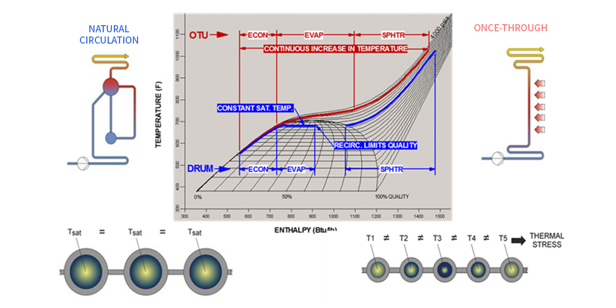
Figure 1
The blue line on the Temperature – Enthalpy (T-H) diagram represents the process at sub-critical pressures. A portion of the water in the waterwalls of the furnace is evaporated into steam at a constant temperature, the internals of the steam drum separates the steam from the water, and then additional heat input superheats the steam. The waterwalls tubes all carry a water/steam mix at the same temperature, the saturation temperature for the operating pressure. Differences in heat absorption from tube to tube results in different percentage of steam in the steam/water mix (aka steam quality), but the fluid temperature remains constant at the saturation temperature.
Note that most utility steam generators world-wide are of the drum type for the sub-critical cycle. While power plants operating at super critical cycles have been around for decades, the current focus on emissions from power plants have increased interest in the super critical cycle due to its better overall plant efficiency (net plant heat rate). See Figure 2.
The steam generators for both the sub-critical and super critical cycles are subject to the same variations in heat absorption at different elevations and around the perimeter of the furnace. See Figure 3. Therefore, the designs of the steam generators for the two cycles need to address the evaporative circuits of the furnace very differently.
The design of a natural circulation steam generator for sub-critical cycles requires proper selection of the number and size of the tubes and pipes in the circuits. The circuits are analyzed to determine the flow induced by heat addition to the furnace walls. The selection of the tubes/pipes is FINALIZED when the flow in the tubes provides adequate cooling of the tubes for the heat absorbed. Note that the flow occurs naturally by the addition of heat; no pumps are required.
-
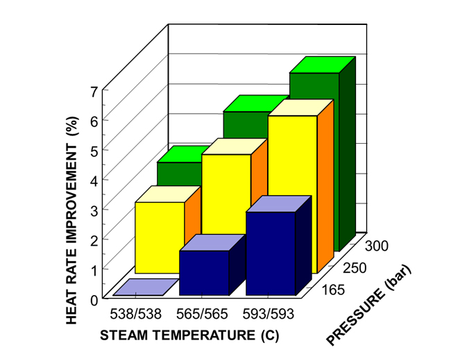
Figure 2
-
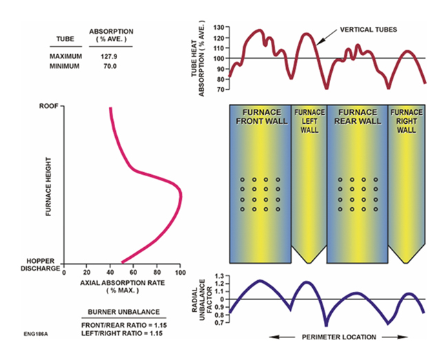
Figure 3
Natural Circulation Steam Generators
For sub-critical power cycles, the natural circulation steam generator is a simple design which provides inherently safe, self-compensating circuits without the need for pumps or orifices.
The basic natural circulation system is comprised of heated riser circuits (furnace waterwall tubes), unheated downcomer circuits and a steam drum. The steam drum receives a water-steam mixture from the waterwalls, separates the steam from the water and supplies the steam free water to the downcomers. The steam is passed on to the superheater circuits.
Flow through the natural circulation system is created by the heat input to the furnace waterwalls which produces a steam/water mixture which is of lower density than the water in the unheated downcomer circuits. See Figure 1.
The flow in the circuits will increase to an equilibrium point so that the gravity head (height of circuit x average density of circuit) in the downcomer and feeders, less friction and shock losses, is equal to the gravity head in the riser circuit , plus friction and shock losses. Figure 2 shows the relationship between the s and the corresponding balance point.
The individual circuits in the system are self-compensating. A circuit which absorbs more heat will have a corresponding reduction in density. The resulting balance point will be at a greater flow than for the average heated circuit. The increased flow provides increased heat transfer in the tubes. Circuits which naturally increase flow with increased heat absorption are commonly described as “self-compensating” or demonstrating a “natural circulation characteristic”. See Figure 3.
Use of rifled / ribbed tubes in the high heat absorption area of the waterwalls provides superior cooling of the tubes. This results in increased margin from Departure from Nucleate Boiling (DNB) while allowing use of carbon steel tubes. See Figure 4.
-
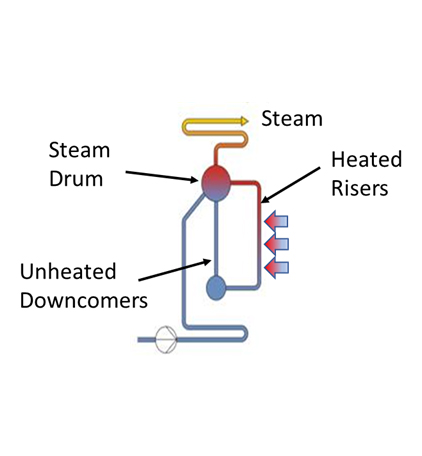
Figure 1
-
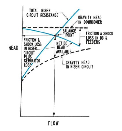
Figure 2
-
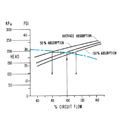
Figure 3
-
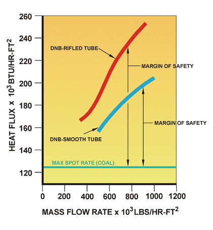
Figure 4